9 Rules for Correct Cabling of the Modbus RS485 Communication Systems
페이지 정보
작성자 Rosella Saylors 작성일24-05-30 09:38 조회9회 댓글0건본문
GSI Grain Storage benefitted in several key ways following installation of the Novus FieldLogger. Six plug and play I/O card slots are standard, and all readings are saved on the removable Compact Flash memory card's128MB storage space for archiving or transfer to a PC. The RJ11 socket in the Unitronics PLCs provides six signal pins. This MJ20-PRG module clicks in the PLC and provides one RJ11 socket for serial communications with a PC. A single complex experiment or several individual experiments using multiple sensors can easily be monitored given the Brainchild's capability to record real-time inputs during one session. Transformers can be of different types, depending on the assembly system: a through cable or a cable with a coiled primary, transformers for assembly on horizontal or vertical bars. Therefore for RS485 communications no crossover cable is used. On some PLC models it is possible to mix RS232 and RS485 communications. This module is powered by the RS232 port from the connecting computer.
Connecting analog instruments is very simple; you just need to connect the phase and neutral cables to the instrument. 04), a Web485 board, and the necessary cables. Setup is the same when multiple meters are interconnected via cables CBL03, except that all meters now need to be set to a different digital address via their front panel. Then use front panel programming to set the baud rate, protocol, digital address, half or full duplex, and other available parameters. If multiple analog input meters or transmitters are digitally addressed in command mode on an RS485 line using the Modbus RTU protocol or the Custom ASCII protocol, the rate becomes about 2 readings per second. A single analog input meter or transmitter can stream readings to a PC at up to 60 readings per second and the Custom ASCII protocol set to continuous (or streaming) model. Using the Solis Data Logging Stick, which uses WiFi to communicate, we were able to set up the inverter to send data to the remote soliscloud service, but we could not find any way to get capture data apart from scraping the basic status page built into the WiFi adapter which only gave watts being produced and daily output.
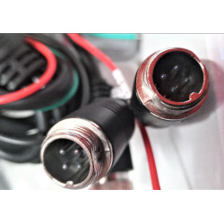
Ability to every one of the heater element can be managed getting a proportional, triac-based controll rounds, by which uses zero-voltage modifying to help attenuate electro-magnetic interference. The data COM port on the base of the Solis inverter uses a small round 4-pin plug with a screw thread to hold it in place when connected. After the experiment is completed, the class can view statistics from the recorded data including instant, average, min and max values. Where can I find RS485 pinouts? For communications, many of their products are equipped with an RS232 or RS485 serial port. In RS232 mode all pins are used for RS232 signals. The RJ11 connector can be used for both RS232 and RS485. In three-phase systems without distributed neutral in which the loads are balanced and symmetrical, an insertion can be made, i.e. two current transformers instead of three can be used; the instrument will calculate by difference the third phase which is not measured directly, considering it as identical to the other two.

Bus Probes are a family of low-power environmental sensors with an RS485 interface. The RS498 bus was working correctly, and we could read values from the device. Read rates vary with counters, since they are normally controlled by the user entry Gate Time. This analog and digital variables data logger featured 8 configurable analog inputs that could read thermocouples, Pt100, Pt1000, voltage and current signals. If a star configuration is unavoidable, special RS-485 repeaters are available which bidirectionally listen for data on each span and then retransmit the data onto all other spans. RS-485 does not define a communication protocol; merely an electrical interface. Both protocols (or communication languages) are built into the instrument’s firmware and are user selectable. The shielding may be braided (be formed by a mesh of thin conducting wires) or be a foil (consisting of a sheet of metal wound around the conductors): the two types are equivalent. This helps to minimize the impact of electromagnetic interference, causing the voltage between the two wires to deviate. Each sensor has two mounting holes for attaching it to walls and other surfaces. This has thick stone walls and a concrete ceiling and has space to install 2 inverters and a battery system later if required.
If you adored this article and you also would like to get more info with regards to rs485 cable i implore you to visit our web page.
댓글목록
등록된 댓글이 없습니다.


